Process and configuration guide

Copper Upward Continuous Casting Process

How molten copper, furnace arrangement, graphite tooling, water-cooled crystallization, controlled withdrawal, and output handling are configured for rod, busbar, flat profiles, tube billet, and reviewed copper sections.

Process sequence

From Melt Preparation to Cast Product

Upward continuous casting withdraws a solidifying copper section upward from the melt through product-specific graphite tooling and a cooled crystallizer. Stable production depends on the complete process window, not on withdrawal speed alone.

Feed-material quality, furnace practice, metal protection, temperature, tooling, cooling water, withdrawal control, strand layout, and collection method all affect the final result. Material claims must be linked to the buyer's standard and test agreement.

  1. 01

    Melt preparation

    Copper is melted and conditioned in a furnace arrangement selected for the raw material, product, operating sequence, and required output.

  2. 02

    Metal holding

    The holding stage supports controlled temperature and metal supply to the casting positions. Atmosphere and melt-protection requirements are defined by the material standard and project review.

  3. 03

    Upward solidification

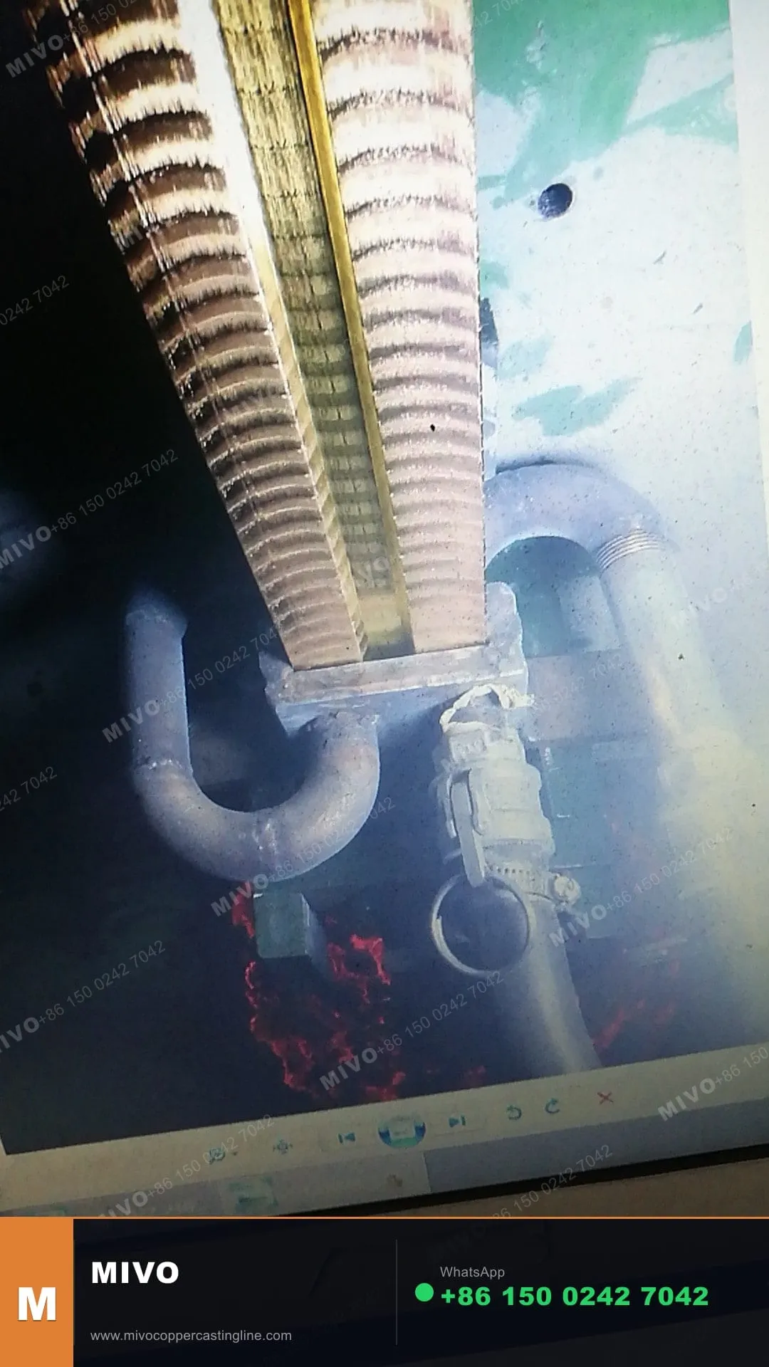
    A graphite die and water-cooled crystallizer establish the required section while the solidifying copper is withdrawn upward under controlled conditions.

  4. 04

    Cooling and withdrawal

    Withdrawal sequence, cooling-water conditions, strand count, and tooling geometry are coordinated around surface stability, section, and production target.

  5. 05

    Output handling

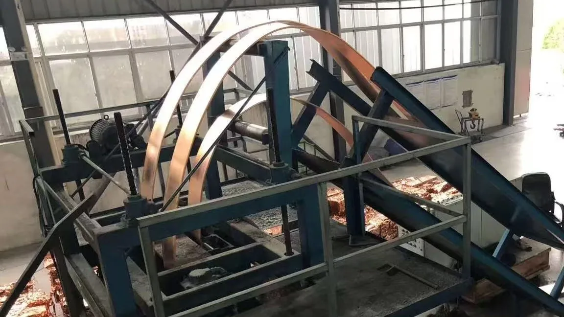
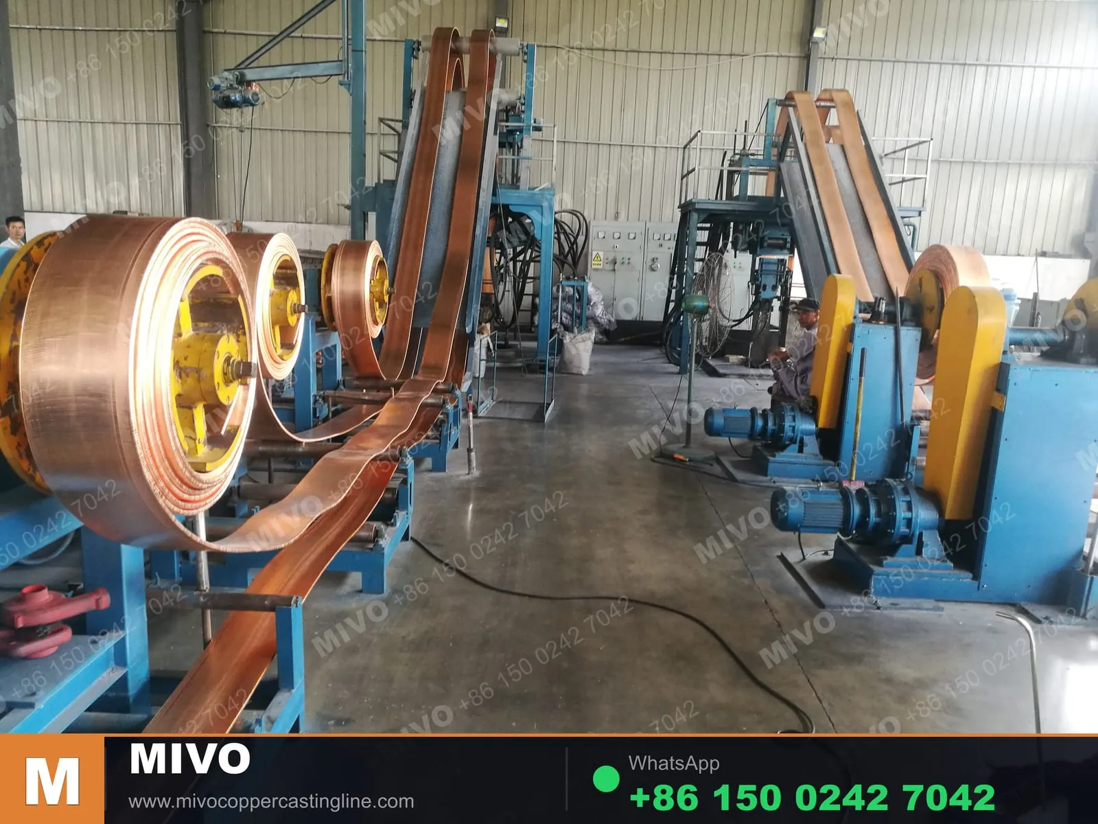
    Round rod may be coiled for downstream wire drawing or forming. Flat profiles may be coiled or cut. Tube billet and drawing-based profiles require route-specific handling.

Product-route effects

How Product Form Changes the Line

A complete upcasting system is configured around the product route. These distinctions help buyers avoid comparing unrelated machine specifications.

Product route Tooling and crystallizer Withdrawal review Output handling
Round copper rod Round graphite die, rod crystallizer, and product-matched protective interfaces Single- or multi-strand arrangement reviewed by diameter and capacity Coiling method and coil weight confirmed with downstream use
Busbar and flat profiles Flat-section die and crystallizer matched to width, thickness, cooling, and strand arrangement Flat-profile stability and the agreed production window drive the withdrawal design Coiling or cut-to-length before downstream straightening, punching, bending, or finishing
Tube or pipe billet Hollow-section tooling reviewed from outside diameter, inside diameter, wall, material, and downstream route Project-specific support and cooling review; not treated as a round-rod substitution Collection and downstream drawing or forming route confirmed before line definition
Drawing-based copper profiles Feasibility reviewed from the section drawing, tolerances, material, and acceptance requirements Confirmed only after tooling, cooling, and production stability review Selected around profile shape, straightness, cut length, coilability, and downstream use
Copper strip handling in an upward continuous casting line

Selection inputs

Configuration Is a Process Decision

Material and standard
Copper grade, raw-material route, sampling, test method, and acceptance values
Product and capacity
Drawing, dimensions, tolerances, downstream use, target output, and operating schedule
Furnace and strands
Melting and holding arrangement, thermal duty, product positions, access, and maintenance
Utilities and layout
Power, cooling water, compressed air, lifting, foundations, workshop dimensions, and environment
Handling and handover
Coiling or cutting, inspection, factory acceptance, export scope, startup, and training

Process support boundary

Process design and startup support are available for selected products and alloy systems. The applicable process scope, technical documentation, commissioning support, and training requirements are confirmed after project review.

Process questions

Copper Upcasting Process FAQ

Process choices are tied to the ordered product and acceptance conditions, not to a generic machine label.

Why does product shape change the copper upcasting line configuration?

Product shape changes the graphite die, crystallizer, cooling path, withdrawal support, strand spacing, coiling or cutting method, maintenance access, and acceptance checks. A rod configuration cannot be assumed to cast flat bar or tube billet without engineering review.
When should semi-continuous casting be considered instead?

Semi-continuous casting should be reviewed for larger round billet, slab, rectangular billet, hollow billet, and copper-alloy feedstock intended for extrusion, forging, or rolling. It is a different equipment and production route from continuous upcasting.

Which information controls furnace and strand selection?

The main inputs are product drawing, material standard, capacity target, operating schedule, raw-material route, strand size and count, coil or cut requirements, power, cooling water, plant layout, and acceptance conditions.

Does the upcasting process always guarantee oxygen-free copper?

No process name by itself guarantees a material result. Oxygen-free copper or Cu-OF must be tied to the agreed raw material, operating controls, sampling, test method, acceptance values, and technical responsibility.

Get in touch

Move from process route to equipment scope

Provide the product drawing, material standard, production target, output handling, and site utilities for a project configuration review.